What Is Automated Mold and How Does It Work?
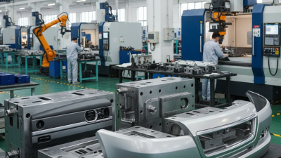
Automated Mold is reshaping how manufacturers design, build, and monitor injection molds. In practical terms, it combines computer-aided design, CNC machining, robotics, sensors, and automated inspection. A robotic arm may load a steel insert, while sensors track temperature, pressure, vibration, and tool wear. Software then compares live readings with production targets. Small changes become visible before they create thousands of defective parts.
The wider automation market shows why this approach is gaining attention. The International Federation of Robotics reported 541,302 industrial robots were installed worldwide in 2023. Grand View Research also identifies automation and digital monitoring as major forces in the global injection molding market. These reports do not measure Automated Mold adoption directly. That limitation matters. Still, they reveal the industrial environment surrounding this technology: manufacturers want repeatable quality, shorter setup times, and less dependence on manual inspection.
John Bozzelli, founder of Injection Mold Consulting, has described the mold as “the heart of the injection molding process.” His point remains practical. If the mold is misaligned, contaminated, or poorly cooled, automation cannot rescue the final product. Automated Mold works best when skilled engineers combine machine data with hands-on experience. It is not magic. A polished dashboard can still hide a worn cavity or a blocked cooling channel. This guide explains the core equipment, workflow, benefits, and risks behind Automated Mold. It also considers where automation genuinely improves production, and where human judgment still deserves the final word.
Defining Automated Molds: Sensors, Robots, and Closed-Loop Control
What Is Automated Mold and How Does It Work?
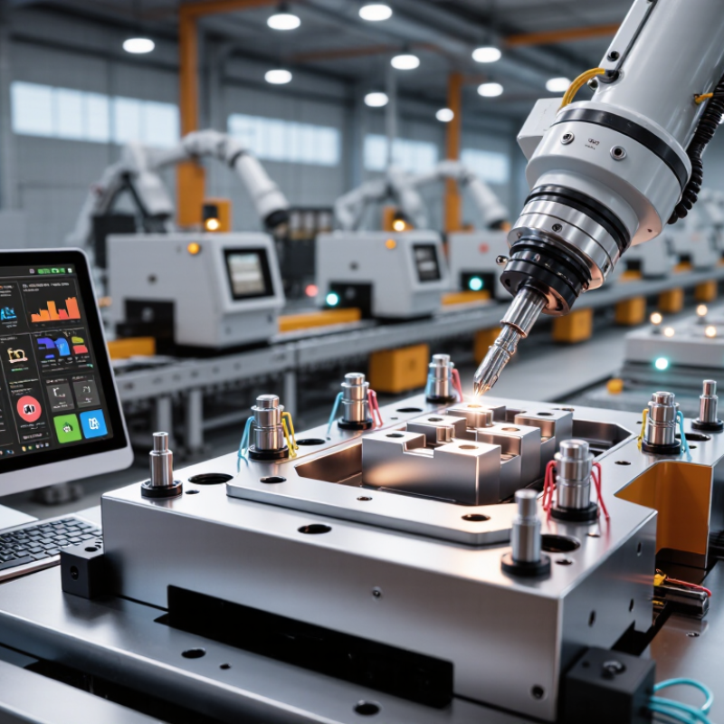
An automated mold is a tooling system that adjusts production with limited manual intervention. It combines sensors, robotic movement, and software-based control. Temperature sensors monitor the mold surface and cooling channels. Pressure sensors track how material fills the cavity. Position sensors confirm whether plates, pins, and ejectors move correctly.
Robots may load inserts, remove finished parts, or transfer components between stations. Their movements follow programmed paths, but the process is not entirely rigid. A camera can detect a misplaced insert before molding begins. A gripper can also change its force when an object feels heavier than expected. Small details matter here. A few millimeters can create flash, short shots, or damaged surfaces.
Closed-loop control connects these observations to immediate corrections. If cavity pressure rises too quickly, the controller can reduce injection speed. If cooling remains uneven, it can extend the cooling cycle. The system compares real-time data with approved process limits, then adjusts selected settings. This reduces guesswork and improves repeatability.
The system is not flawless. Sensors can drift, wiring can loosen, and software may respond to bad data. Human inspection still matters, especially during setup changes or unusual defects. A poorly placed sensor may report a clean process while the part tells a different story. Engineers should review trends, calibration records, and physical samples together. That extra check can feel slow, but it often prevents larger production losses.
Core Components: EUROMAP 67 Interfaces, Actuators, and Process Sensors
Automated mold systems connect the molding machine, mold, robot, and control software into one coordinated cell. The EUROMAP 67 interface provides a structured communication link between the machine and automation equipment. It can exchange signals for mold status, ejector movement, core functions, robot readiness, and safety conditions. Clear signal mapping matters. A single incorrect input can stop production or damage a component.
Actuators perform the physical work. Servo drives may move a robot or mold mechanism with controlled speed and position. Pneumatic cylinders can handle gripping, clamping, or part removal. Process sensors provide the system with evidence. Pressure sensors monitor cavity filling, while temperature sensors track heating stability. Position sensors confirm whether an ejector or core has reached its target. Without these signals, the controller is operating partly blind.
Tips: Confirm every EUROMAP 67 signal during commissioning. Test one movement at a time. Record the expected response and actual response. Check wiring, polarity, timing, and emergency-stop circuits. Do not assume two machines interpret every signal identically. This is where many avoidable faults begin. Sensor readings can also drift, especially near heat and vibration. Calibration should be scheduled, not remembered only after quality problems appear. A practical weakness remains: automation improves consistency, but poor setup makes errors repeat faster.
What Is Automated Mold and How Does It Work?
Core Components: EUROMAP 67 Interfaces, Actuators, and Process Sensors
This illustrative injection-molding cycle shows how process sensors provide feedback while actuators control mold movement and injection conditions. A EUROMAP 67 interface exchanges machine status, safety signals, start commands, and robot-handling coordination data between the molding machine and automation equipment.
Step 1—Digital Mold Design with CAD/CAM and DFM Standards
What Is Automated Mold and How Does It Work?
Step 1—Digital Mold Design with CAD/CAM and DFM Standards
Automated mold production begins with a precise digital model. Engineers create the part and mold geometry using CAD software. The model includes cavities, cores, cooling channels, ejector locations, and draft angles. Every millimeter affects filling, cooling, and final accuracy.
CAM systems then convert approved geometry into machining instructions. Before cutting begins, engineers review the design against DFM standards. These standards help identify thin walls, sharp corners, uneven thickness, and difficult undercuts. A small error here can become expensive steel rework later. The first draft is rarely perfect.
Design reviews also use digital simulations. Engineers can estimate material flow, cooling behavior, shrinkage, and possible distortion. They check whether the mold can open cleanly and release the finished part. Practical experience still matters, because software may miss unusual production conditions. A simulation can look convincing and remain incomplete.
Clearances deserve special attention. Moving components need enough space to operate without binding. However, excessive clearance can create flash or poor alignment. Engineers compare digital measurements with machining limits and inspection data. They also consider tool access, maintenance, and expected production volume. Good design is not only about making the part; it is about making the mold serviceable. When assumptions seem uncertain, teams should record them and test the riskiest feature before full machining.
Step 2—Automated Injection, Cooling, Ejection, and Part Handling
What Is Automated Mold and How Does It Work?
Automated injection begins when dried plastic pellets enter a heated barrel. A screw melts the material and pushes it into a closed mold under controlled pressure. Sensors monitor melt temperature, injection speed, and cavity pressure. These readings help technicians detect short shots, flash, or unstable filling before defects spread.
Cooling follows immediately. Water or oil moves through internal channels, removing heat from the mold and part. Uneven cooling can cause warpage, sink marks, or difficult release. When the part reaches its target temperature, the mold opens. Ejector pins, sleeves, or air assist remove it without crushing thin features. A robot or conveyor then transfers the part to inspection, trimming, packing, or the next process. Timing matters. A delayed handoff can slow the entire cell.
Tips: Keep cooling channels clean and verify flow rates during routine checks. Watch the first parts after a material or mold change. Small temperature shifts can alter shrinkage. Automated systems reduce repetitive work, but they do not eliminate judgment. In my experience, alarms are useful only when their limits reflect real production conditions. Overly sensitive settings create noise. Loose settings hide problems. A part may look acceptable at the machine and fail later during assembly. That is why dimensional checks and visual inspection should remain part of the process. One missed detail can become a repeated defect.
Evaluating Performance with OEE, Cycle Time, Scrap Rate, and ISO 20430
What Is Automated Mold and How Does It Work?
Evaluating Performance with OEE, Cycle Time, Scrap Rate, and ISO 20430
An automated mold system coordinates mold movement, material delivery, cooling, ejection, and part handling. Its value becomes clearer through measurable production data. OEE combines availability, performance, and quality into one practical indicator. A machine may run for eight hours, yet frequent stops can reduce availability sharply. Planned maintenance should remain separate from unexpected downtime.
Cycle time reveals how long each molding cycle takes. Operators should compare actual cycles with validated target times, not optimistic estimates. A two-second increase may seem minor, but it can remove hundreds of parts from a daily schedule. Scrap rate adds another warning. Flash, short shots, warpage, and contamination often signal unstable temperature, pressure, or material flow. The data needs physical inspection.
ISO 20430 focuses on safety requirements for injection molding machines, including safeguarding and control functions. It does not replace OEE or quality records. Instead, it provides a structured safety reference for automated equipment design and operation. In practice, teams can review guard interlocks, emergency stops, access points, and unexpected mold movement during commissioning. My first performance dashboard looked impressive, but it ignored brief sensor faults. That was a mistake. Clean data is not guaranteed. Sensors drift, operators classify downtime differently, and a low scrap rate can hide slow production. Regular audits, traceable records, and floor-level observations make these metrics more trustworthy. Numbers need context.