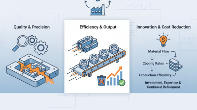
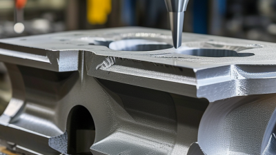
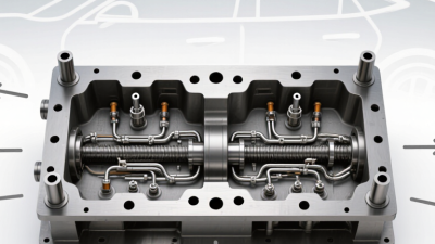
A Die Casting Mold shapes more than the outer form of a component. It affects dimensional accuracy, surface finish, cycle time, and the cost of later production. For global buyers, the right choice depends on alloy, part geometry, annual volume, and maintenance capacity. Small details matter. A deep rib, thin wall, or difficult ejector location can change the tooling decision.
Casting researcher John Campbell’s work offers a useful principle, paraphrased here: “Control metal flow and solidification before chasing cycle time.” That guidance helps frame the choices ahead. Buyers may compare hot-chamber and cold-chamber molds, single- and multi-cavity designs, and family or unit tooling. Each has trade-offs. A multi-cavity tool can raise output, but only when filling and cooling remain balanced. More cavities are not automatically better.
This guide examines the main mold types, their practical strengths, and the questions buyers should ask suppliers. It also considers tool steel, cooling layout, venting, ejection, and maintenance access. Those details can decide whether a mold performs reliably across long production runs. A specification sheet rarely tells the whole story. Ask for drawings, process assumptions, and evidence from comparable projects. Then check them carefully. Even experienced teams can overlook a small design constraint. A little doubt is useful.
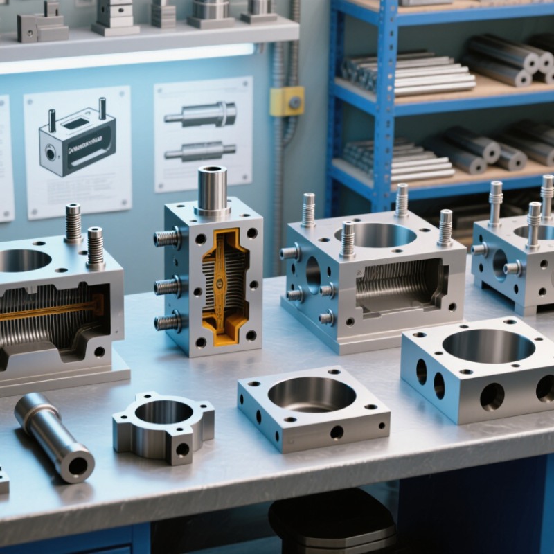
High-pressure die-casting dies are built to manage fast metal flow and substantial loads. Injection pressures commonly reach 70–100 MPa, though the working range depends on the alloy, machine, and part geometry. That figure describes pressure in the injection system; pressure inside the cavity can differ during filling and intensification. The distinction matters. A thin-walled housing with long flow paths may need different gate placement and venting from a compact bracket. Air traps, cold shuts, and uneven filling can still occur when pressure is high.
For the die, pressure is only one design consideration. The projected area of the casting helps determine the required clamping force, while the parting line, inserts, and locking features must resist separation and flash. Cooling channels also need careful placement: a hot spot near a thick boss can extend cycle time and increase thermal stress. Small details count. A vent that is too shallow may clog; one that is poorly placed may leave trapped gas. Process trials should verify fill behavior, die temperature, and casting quality rather than treating 70–100 MPa as a guaranteed setting. A useful design review can question assumptions, because even a well-engineered die may need adjustment after the first shots.
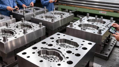
For aluminum cold-chamber die casting, molten metal is commonly poured at about 650–700°C. That range is a working window, not a fixed recipe. The correct setting depends on alloy chemistry, shot size, transfer time, and the distance between furnace and die. A temperature reading at the furnace may not match the metal entering the shot sleeve. Heat is lost during ladling. This difference matters.
If the melt is too cool, it may freeze early. Thin ribs and long flow paths are vulnerable. Excess heat can increase oxidation, gas pickup, and die thermal load, while also prolonging solidification. Operators should confirm actual melt temperature near the pour, using a calibrated instrument and a repeatable sampling method. Then trial parts should be checked for fill, porosity, and surface quality. It is easy to treat 675°C as a magic number; it isn’t. A small adjustment can help, but temperature alone cannot fix poor venting or an unbalanced gate. The target may need revision.
Hot-chamber dies are a practical choice for many zinc components because zinc melts at a relatively low temperature. Pure zinc melts at about 420°C, although alloy compositions can shift the working range. In a hot-chamber machine, the injection system’s gooseneck sits in the molten metal. This short path supports quick, repeatable shots and limits the handling needed between melting and injection. That matters. For small housings, connectors, and finely detailed parts, steady filling can help reproduce thin ribs and crisp edges.
The lower melting temperature does not remove the need for careful process control. Operators still monitor melt temperature, injection pressure, and die temperature; a few degrees or a worn vent can change surface quality. A well-designed die also needs balanced cooling and vents that let trapped air escape. Still, it is not a free pass. Zinc can freeze in narrow sections if the metal cools too soon, while poor venting may leave small voids or marks. One detail buyers sometimes overlook is maintenance: gates and vents need inspection over repeated production runs. The setup is efficient, but the first trial may reveal details the drawing did not.
Approximate melting points of selected pure metals commonly associated with die casting. Zinc melts at about 419.5°C, making it well suited to hot-chamber processes. Actual alloys may melt over a temperature range.
In gravity die casting, molten metal enters a reusable metal mold under its own weight. No high-pressure injection forces the fill. This slower flow makes gate and vent design especially important. A narrow passage can cool too soon, while trapped air may leave pores or incomplete sections. Small details matter.
The mold is usually preheated before pouring, helping reduce thermal shock and uneven filling. Operators control metal temperature, pour rate, and cooling time for each production run. For an aluminum housing, a foundry may inspect thin ribs and corners closely, since these areas can freeze before the thicker body fills. Still, gravity casting is not ideal for every shape. Very thin walls or intricate internal passages may require another process, or a carefully designed core. That choice deserves review.
Buyers should ask how the mold handles venting, parting lines, draft angles, and expected production volume. These details affect casting quality, tool life, and trimming work. A well-made mold can produce consistent parts, but it cannot erase poor process control. Even experienced teams sometimes need trial pours to adjust the design. That is normal, though it should be planned.
| Mold configuration | How the metal enters the die | Common alloy suitability | Typical applications | Key benefits | Buyer considerations |
|---|---|---|---|---|---|
| Static permanent mold | The mold remains stationary while molten metal is poured into the cavity and fills it under gravity. | Commonly used for aluminum and copper-based alloys; alloy choice depends on mold materials and process conditions. | Brackets, housings, pulleys, and other components with relatively straightforward cavity layouts. | Reusable metal tooling can support repeatable production and a generally sound surface finish. | Part geometry must allow reliable filling and removal; gating, venting, and temperature control require careful design. |
| Tilt-pour permanent mold | The mold is tilted during pouring so metal enters the cavity progressively, then is returned toward its working position as filling completes. | Often selected for aluminum alloys and other alloys compatible with permanent-mold casting. | Castings where controlled filling can help reduce turbulence, including selected automotive and industrial components. | Progressive filling may reduce metal turbulence and oxide-film entrainment compared with an unsuitable abrupt pour. | Requires a tilting mechanism and a validated pouring sequence; results depend on part geometry and process control. |
| Permanent mold with expendable cores | Metal fills a reusable metal die by gravity around a sand or other expendable core; the core is removed after casting. | Commonly applied to aluminum alloys; suitability depends on core design, alloy, and casting requirements. | Parts with internal passages or cavities that are difficult to form with reusable metal core slides. | Combines reusable outer tooling with the geometric flexibility of expendable cores. | Core manufacture, placement, removal, and dimensional consistency add process steps and quality checks. |
| Multi-cavity permanent mold | A single mold contains two or more cavities, which are filled through a shared or balanced gating arrangement under gravity. | Used with suitable permanent-mold alloys, particularly where part size and production requirements allow balanced filling. | Small to medium components produced in repeated quantities, such as fittings and compact hardware. | Can produce multiple parts per pour and improve output when cavities fill consistently. | Cavity balance, metal distribution, cooling, and ejection must be engineered to avoid variation between parts. |
Note: These configurations describe common gravity permanent-mold arrangements. Actual alloy suitability, achievable tolerances, surface finish, and production rate depend on part design, tooling, and process validation.
Vacuum-assisted dies remove air from the cavity before molten metal enters. A pressure below 10 kPa absolute equals less than 100 mbar. At sea level, standard atmospheric pressure is about 101.3 kPa, according to the National Institute of Standards and Technology. That leaves a large pressure difference to manage. The number matters, but stable timing and sealed vents matter just as much.
NADCA’s Die Casting Process Manual describes vacuum as a way to reduce gas trapped during filling. Lower cavity pressure can help limit gas porosity, which is important when castings face heat treatment or pressure testing. However, a gauge reading alone does not prove the casting is sound. Leaks, slow valve response, or a poorly placed vacuum line can undermine the target. Shop-floor results can vary; even a well-designed die needs careful trials.
Tips: Check absolute pressure at the cavity, not only at the pump. Log pressure alongside shot speed and valve timing. A small leak can change the result. Keep one imperfect trial in the record; it may reveal a setup issue that polished samples hide.